


The one we have all been waiting for! ;-)
Designed by the Swedish A&E Design company in 1974 the Turn-o-matic came to may shops and waiting rooms around the world. With its large flipping numbers and an obnoxious buzzer that when it sounded made everybody in the room look up to the big eye on the wall, then down on the ticket in their hands, do the maths and estimate how long they would need to wait for their turn.

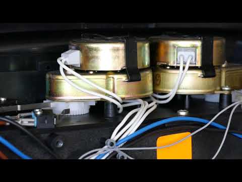
Each digit is driven by a synchronous motor through a gearbox. Each also has a cam wheel and a microswitch that controls the moment that the motor switches of. On the ones there is an additional cam wheel and switch to increment the tens when the ones go from nine to zero. I got it without any connecting gear, like the cables, buttons and power supply. So I had to reverse engineer and construct something myself to get it working.


Videos:

For whoever may need it, this is how to connect it:


I don't have any practical use for it, but just like to make it buzz and flip whenever I want. So much better than waiting!
Designed by the Swedish A&E Design company in 1974 the Turn-o-matic came to may shops and waiting rooms around the world. With its large flipping numbers and an obnoxious buzzer that when it sounded made everybody in the room look up to the big eye on the wall, then down on the ticket in their hands, do the maths and estimate how long they would need to wait for their turn.
Each digit is driven by a synchronous motor through a gearbox. Each also has a cam wheel and a microswitch that controls the moment that the motor switches of. On the ones there is an additional cam wheel and switch to increment the tens when the ones go from nine to zero. I got it without any connecting gear, like the cables, buttons and power supply. So I had to reverse engineer and construct something myself to get it working.
Videos:
For whoever may need it, this is how to connect it:
- White-black: 24V AC (about 0.5 A will do).
- Close brown-black to increment the ones (with buzzer)
- Close blue-black to increment the tens (without buzzer)
I don't have any practical use for it, but just like to make it buzz and flip whenever I want. So much better than waiting!
Comment