Welcome!

Welcome to the forum for collectors, restorers and fans of flip clocks. Please Sign Up if you would like to take part.

By the way, signing up is free..

Announcement

Collapse
No announcement yet.

The World's First Flip Clock - History Rediscovered

Collapse
X
 
  • Filter
  • Time
  • Show
Clear All
new posts

    The World's First Flip Clock - History Rediscovered

    How can it be that I've been messing around with flip clocks about 10 years (7 years pretty heavily) and I have just now re-discovered the history the world's first flip clock?!

    The story is much more interesting and more cool than you may know.

    First Flip Clock Facts
    Nationality of Inventor: Austrian
    Country of Manufacture: Germany
    Name of Manufacturer: Lenzkirch Clock Factory
    Year of Manufacture: 1894

    Yes ... 1894. Almost Ten Years before the Plato Clock was patented in the United States. And this clock was a true horizontally flipping flip clock - lost to history evidently - but not any more.

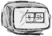
    Here it is Flip Clock Fans:
    The first flip clock was conceived by Austrian inventor and engineer Josef Pallweber in 1890 and produced in Lenzkirch, Germany by the world-renowned Lenzkirch Clock Factory between 1893-1894.

    Josef Pallweber was issued German patent No. 54093 on October 27, 1890 for his "Uhr mit Zahlenwechsel durch Herabfallen doppelseitig bezifferter Täfelchen" (Clock with numbers changing by falling double-sided numbered tablets.

    Pallweber's patent was first described to the public in the December 1 1890 issue of The German Journal for Clock-Makers (Deutsche Uhrmacher Zeitung) and the production announced in the journal exactly 3 years later in 1893.

    Click image for larger version  Name:	76e38839c1ae8db0c5ef8b2d4c70a864.jpg Views:	0 Size:	71.9 KB ID:	19432

    Using the Pallweber design, The German Lenzkirch Clock Factory (Aktiengesellschaft für Uhrenfabrikation Lenzkirch) crafted the world's first flip clock in 1894. These clocks were very ornate, as was the practice of the Lenzkirch clock makers, and interestingly enough - the first flip clock was a pendulum clock.

    First Digital Clock

    Click image for larger version  Name:	77804001_1_x.jpg Views:	0 Size:	137.3 KB ID:	19440 Click image for larger version  Name:	pallweber_number_plates.jpg Views:	0 Size:	165.2 KB ID:	19441

    Josef Pallweber also invented the world's first digital clock (a rolling plate affair) and the world's first digital watch.

    By no later than 1884 the world's first digital pocket watches were created using a Pallweber (jump number) design. They were produced by IWC from 1885-1887 (as well by by other watch makers) and are considered to be among the most famous of IWC pocket watches. (IWC stand for: International Watch Company, Schaffhausen, Switzerland).

    Click image for larger version  Name:	1886 watch.jpg Views:	0 Size:	104.0 KB ID:	19442

    The Legacy Continues
    The Pallweber Name came back to prominence when in 2018 the IWC (International Watch Company) of Switzerland release several heritage watches to commemorate their 150 year anniversary. One of these was a Pallweber Jump Number pocket watch. But more excitingly, IWC redesigned and produced a Pallweber inspired Jump Hour and Jump Minute watch (these watches range in price from about $30,000 to $50,000 new and were released in very limited quantities).

    Click image for larger version  Name:	IWC-Tribute-To-Pallweber-Edition-150-Years-IW505002-1.jpg Views:	0 Size:	164.3 KB ID:	19433

    So the inventor of the flip clock, we can proudly say, was the incredibly prolific inventor (he has other interesting inventions beyond clocks and watches), Austrian born and German resident, Josef Pallweber. Who knew?!

    For more history - see the article: The First Flip Clock
    ~ Mackey Site Administrator
    If you have any questions/comments Contact Me
    If you're not a member, you should consider joining!

    #2
    Below is an image that I combined and cleaned up from the German Patent (see pdf of original on this site). I have also translated the German into English (of course thanks to German OCR software and Google. Luckily, German to English translates relatively easily.


    Click image for larger version  Name:	patent-full_lg.jpg Views:	0 Size:	275.8 KB ID:	19436

    PATENT
    No 54093
    Class 83 Clocks

    Issued October 27, 1890

    JOSEF PALLWEBER IN MANNHEIM.

    Clock with numbers changing by falling double-sided numbered tablets.

    Patented in the German Empire on February 28, 1890

    The subject of the invention is a clock in which the hour and minute numbers appear put together on metal plates in two halves, without this being recognizable at some distance.

    The drive A drives the minute drum attached to shaft B by means of a gear ratio (Fig. 2), in which 60 leaves are suspended, which carry the upper half of a number on one side and the lower half of the following number on the other so that the two sides of two successive leaflets add up to an integer if one leaflet is up and the second hangs down, as can be seen from FIG. B. the upper leaflet C carries the upper half of the number 51 and rests with its edge above the edge of the cutout of the plate or disk D and the tip E of the same until the rotation of the shaft B with the drum has advanced so far that the leaf C slides past the tip E and falls down, so that the back of the same with the lower half of the number 52 becomes visible, while the following upright leaf bears the upper half of the number 52, and so on.

    The minute drum consists of two perforated disks F, the rings of which are pierced by 60 holes each, in which the pegs of the leaves hanging in between are easily movable. In the same way, the drum of the number of hours (Fig. 3) consists of two disks H, fixed on the axis G, with 24 holes each, in which the 24 leaves hang easily movable, which carry the number of hours twice. The shafts B and G are mounted on the disk D.

    Every time after the shaft B has made one turn, the shaft G has to make a 1/24 turn and then has to stand still for that long. For this purpose, a disk with a nose J, Fig. 5, sits on the shaft B, which pushes the arm K1 of the lever K inwards with one revolution of the shaft B and then suddenly releases it as soon as the nose J over the end of the same has slipped away, so that the spring L then pulls the lever K, which rotates around the pin M, against the disk D and thereby the shift hook N attached to the end of the lever K turns the shifting wheel O sitting on the shaft G so that the next hour ahead becomes visible by means of the leaflets.

    The ratchet wheel 0, Fig. 5, protrudes with a few teeth in front of the disk D, Fig. 1, to turn it with the nail of a finger and the. Being able to set the number of hours correctly; Furthermore, a button P is attached in front of the disk D, which sits on the axis Q, the gear wheel R of which engages in a wheel of the minute drum (Fig. 3), so that the shaft B can be turned from the outside in one direction and the number of minutes set correctly can.

    A perpendicular is attached to the back of the clock, and the second hand is set in motion by a gear ratio.

    PATENT CLAIMS: 1. For clocks to display the hours and minutes, the arrangement of a pair of disks (F) that are turned evenly
    Sheet metal panels, which are held upright by a nose (E) in the reading opening until the number changes and then fall down, and which have the upper half of a digit or several digits on one side and the lower half of the digits on the other side wear the following number so that a hanging and an upright leaf together form a complete number that is visible through the opening.

    2. The device characterized by claim I. for displaying the hours and minutes in the version in which the movement from the minute shaft (B) to the hour shaft (G) by means of a nose J attached to the shaft (B) Disc is transferred, which with each rotation pulls the arm K1 of the spring-loaded lever K carrying the pawl N and then lets it fall off its nose, by means of the pawl N around one tooth of the ratchet wheel (O) attached to the hour shaft (G) to turn.

    For this purpose 1 sheet of drawings.
    ~ Mackey Site Administrator
    If you have any questions/comments Contact Me
    If you're not a member, you should consider joining!

    Comment


      #3
      Click image for larger version

Name:	fig1.jpg
Views:	434
Size:	92.7 KB
ID:	19437 Click image for larger version

Name:	fig2-3.jpg
Views:	442
Size:	129.6 KB
ID:	19438 Click image for larger version

Name:	fig4.jpg
Views:	441
Size:	27.2 KB
ID:	19439
      from: Deutsche Uhrmacher Zeitung - Fachblatt für Uhrmacher XIV Jahrgang * Berlin, den 1 Dezember 1890 No. 23 pages 178-179

      Pendulum clock with numbers that change by falling double-sided numbered tablets

      (D. R. Pat. No. 54093.)

      The inventor of the well-known grandfather clocks with jumping numbers, Joseph Pallweber in Mannheim, has just received a new patent for a pendulum clock in which the time indication is visible in the same way as with those clocks through two cutouts in the dial; the construction of the movement, through which these time indications are effected, is, however, quite different from that of the clocks mentioned above and so original in its nature that the description of the same should be of interest to any person skilled in the art.

      In the accompanying drawings, the main parts of the relevant mechanism are shown, namely Fig. 1 gives a view of the dial, while in Fig. 2 and 3 the clockwork in the two side views and in Fig. 4 the mechanism of the hour indication is particularly shown.

      The time indicated in FIG. 1 is 10 o'clock 51 minutes. Each of the two numbers 10 and 51 is made up of two movable sheet metal plates, the pivot points of which are in the middle of the numbers. The upper plate is upwards (calculated from its pivot point), its upper edge lies on the nose E and/or El of the dial section is on and is painted on the front with the upper half of the relevant number, through which the section is visible on the dial. Seen from a distance, the small space between the two platelets in the middle of the numbers disappears almost completely. The transverse lines visible below the numbers are the lower edges of the previous number plates. The change in numbers takes place in such a way that the drum, to which the platelets with the minute numbers are attached, is set in slow rotation by the clockwork, so that, depending on the lapse of one minute, the edge of the upper platelet C is free from the nose E. and folds it down, revealing the back of the same with the lower half of the number 52, while the following upright plate bears the upper half of this number, etc.

      The minute roll ordered from two hinged disks F, Fig. 3, the wreaths of which are each provided with 60 holes, in which the pegs of the platelets hanging in between are easily movable with the minute numbers. This minute drum is mounted on the shaft B in such a way, that its circumference comes right up to the back of the dial D. The rotation of the drum is caused by the mainspring A, which initially drives an ordinary pendulum clockwork, from whose minute wheel a conical or cantilever wheel engages a similar wheel on the shaft B of the minute drum and turns it once in an hour. Because the platelets are all of exactly the same length, each platelet falls off the nose E, FIG. 1, in the manner described above every minute.

      The hour drum H, Fig. 2, is mounted with its shaft G in the same way as the minute drum close to the back of the dial D and carries within its wheel rims 24 easily movable, equally long plates with the number of hours. The numbers can be from 1–24 or twice from 1–12. Since the new number of hours must appear every time at the same moment when the minutes change from 59 to 0, the rotation of the hour drum must not be gradual, but must occur suddenly at the right moment. The mechanism shown in particular in FIG. 4 is used for this purpose.

      A helical disk J is attached to the shaft B of the minute drum, on the circumference of which the arm K1 of a long lever K rotatably arranged at M on the dial D rests continuously, which is effected by the pressure of the spring L. At the outermost end of the lever K the pawl N is movably seated, which by its own weight constantly engages in one of the 24 ratchet teeth of the wheel O, which is attached to the shaft G of the hourly drum. In the course of the rotation of the minute drum, the helical shape of the disc J moves the lever K inwards from the dial D so that the pawl N located at the upper end of K engages the next ratchet tooth of the wheel 0. The worm J is placed on the shaft B in such a way that at the 59th minute the end of the arm Kl has reached the highest point of the worm. As soon as the following minute 0 appears, the lever K snaps from the highest to the lowest point of the circumference of the worm under the pressure of the spring L, and the holding pawl N gives the hour drum one revolution, so that the plate C1, Fig. 1, from the Nose El on the dial section falls off and the new number of hours becomes visible. In order that the ratchet wheel O cannot be backfilled again by the slow inward movement of the pawl N which then takes place again, a pawl N1 is located above the same, which prevents this.

      As can be seen from Fig. 4, the ratchet wheel O is with a few teeth on the front surface of the dial D also. This enables you to turn the wheel O with your fingernail and thus set the correct number of hours. (See also Fig. 1 at O.) In order to be able to set the minute drum to the correct time, see in front of the dial D, Fig. 1, 2 and 3, a button P, which sits on the front end of the shaft Q. , au the rear end of which a drive R, FIG. 2, engages in the wheel S which is rotatable on the minute wheel shaft with full friction and which sets the minute drum in rotation. By turning the button P, the correct number of minutes can thus be set in a convenient manner. The second hand sits on the extended front pin of a special drive, which is set in rotation by the clock's impeller.
      ~ Mackey Site Administrator
      If you have any questions/comments Contact Me
      If you're not a member, you should consider joining!

      Comment


        #4
        Translated from:
        Deutsche Uhrmacher Zeitung - Fachblatt für Uhrmacher XVII Jargang * Berlin, den 1 Dezember 1893 No. 23 No. 23 page 181


        Click image for larger version  Name:	2ndarticle.jpg Views:	0 Size:	207.1 KB ID:	19444 Grandfather clock with changing hour and minute digits.

        Many of our dear readers will still remember the description of a "pendulum clock with number change by falling double-sided numbered tablets", which we brought three years ago (see No. 23, year 1890). The inventor of that watch, Mr. Jos. Pallweber, wanted to create a more practical time indication, as it is similar to z. B. is required in pocket watches with jumping numbers, but in a more reliable mechanism.
        The accompanying drawing shows the dial of such a clock on a reduced scale and thus illustrates the great clarity of the time indication according to the expression "ten o'clock fifty-one minutes" used in the railway industry.
        It is certainly no more difficult to use this phraseology than to say, "Nine minutes to eleven o'clock". In addition, the audience is usually used to counting from five to five minutes; most people would therefore say, "Ten minutes to eleven o'clock," if the same time were written on an ordinary clock face. However, this creates inaccuracies which are becoming increasingly unacceptable today, when a single minute is all too often important.

        The time shown in the drawing is therefore entirely up to date, and our dear readers should be interested in it. to hear that the idea on which that time is based has now been put into practice, in that the Pallweber’s patented grandfather clock has recently been manufactured in an even better form in Lenzkireit and has been manufactured by G. Landmann & Cie. in Frankfurt a. M., to which the inventor belongs as a partner, is put on the market. The patented system of this clock is not to be confused with the "grandfather clocks with jumping numbers" that appeared a few years ago but just as quickly disappeared from the scene; the mechanism of the present clock rather ensures that it functions reliably. These clocks are therefore likely to become well established in the trade in their present form.

        Click image for larger version

Name:	fcf-logo.jpg
Views:	390
Size:	40.4 KB
ID:	19469

        Postscript:
        To set the record straight - some people have taking to displaying the following image along with videos, blogs and the like when speaking of Joseph Pallweber. This is not an image of Pallweber. It is Abraham Cahan (1860-1951) Abraham "Abe" Cahan was a Lithuanian-born Jewish American socialist newspaper editor, novelist, and politician who has no relationship at all to Pallweber or clockmaking.

        Click image for larger version  Name:	Cahan-Abraham2.jpg Views:	0 Size:	36.4 KB ID:	19466
        ~ Mackey Site Administrator
        If you have any questions/comments Contact Me
        If you're not a member, you should consider joining!

        Comment


          #5
          Interesting research, thanks for sharing.

          Comment


            #6
            Such cool, cool, cool info!! Thanks for posting!

            Comment


              #7
              Originally posted by Engineer View Post
              Such cool, cool, cool info!! Thanks for posting!
              As a watch guy, I thought that you'd appreciate it!
              ~ Mackey Site Administrator
              If you have any questions/comments Contact Me
              If you're not a member, you should consider joining!

              Comment


                #8
                Originally posted by Mackey View Post

                As a watch guy, I thought that you'd appreciate it!
                Oh my gosh...my brain exploded! I really liked the old-school schematics.

                Comment


                  #9
                  I feel a project and a new video coming along.... Too bad it's not an actual flip clock.

                  Great story, good read!
                  Josef Pallweber - Incomplete Digital Clock Movement Only - 19c - 002 23 patent | Antiques, Antique Clocks, Mantel/Carriage Clocks | eBay!

                  Comment


                    #10
                    And finally, introducing the World's First Flip Clock to YouTube


                    ~ Mackey Site Administrator
                    If you have any questions/comments Contact Me
                    If you're not a member, you should consider joining!

                    Comment


                      #11
                      Hey Mackey,
                      Great job sharing the real deal history of these clocks. The video turned out great!

                      Comment


                        #12
                        Many thanks for getting all this excellent info all organized in one place! It was a treat to read through, it's amazing how much more history there is hidden just out of sight. Rock on sir!

                        Comment

                        Working...
                        X