

Hello flip clock friends I have been slacking posting my projects for more then 1 year. I have a lot of projects finished and unfinished. I unfortunately don't have to many pictures to show at the moment. But trying to change that.
The white Sony TFM - C650WL was one of the first Sony flip clock radios I bought. I really loved it because of the 230v 50hz version. Most of my other flip clocks and flip clock radios are 100-120v 60hz.
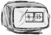
I also acquired the dark grey Sony TFM - C650WL 230v 50hz and the red japanese version which are named TFM-C420. So in the picture I have changed over the red "hood" from the japanese TFM-C420 to my white TFM-C650WL.
I also fixed the blacklight with two 5mm UV-led that I grind flat and polish to give a wider light spread. I use a ac to dc led driver. For me it doesn't create any noise to the radio plus we don't really have AM over here in sweden.
I had a lot of problems with the led going bad or slowly became weaker after a couple of weeks. A friend who know much more about electronics then me said that maybe the cheap led driver leaks ac and that slowly destroys the led. I did connect the led driver to my oscilloscope and it wasn't a super clean signal but I have no clue if it is bad enough to cause this problem. Instead I created a circuit to clean up the dc with a bridge rectifier that goes into a LM317 adjustable voltage regulator. So now I can adjust the light output very precisely and under drive the led's instead. I have not tried this long enough to see if this fixes the problem or if it's just bad led's I own. UV led's seems to have a shorter life span?
All of them are in good condition and I need to completly finish them and post my results.


The white Sony TFM - C650WL was one of the first Sony flip clock radios I bought. I really loved it because of the 230v 50hz version. Most of my other flip clocks and flip clock radios are 100-120v 60hz.
I also acquired the dark grey Sony TFM - C650WL 230v 50hz and the red japanese version which are named TFM-C420. So in the picture I have changed over the red "hood" from the japanese TFM-C420 to my white TFM-C650WL.
I also fixed the blacklight with two 5mm UV-led that I grind flat and polish to give a wider light spread. I use a ac to dc led driver. For me it doesn't create any noise to the radio plus we don't really have AM over here in sweden.
I had a lot of problems with the led going bad or slowly became weaker after a couple of weeks. A friend who know much more about electronics then me said that maybe the cheap led driver leaks ac and that slowly destroys the led. I did connect the led driver to my oscilloscope and it wasn't a super clean signal but I have no clue if it is bad enough to cause this problem. Instead I created a circuit to clean up the dc with a bridge rectifier that goes into a LM317 adjustable voltage regulator. So now I can adjust the light output very precisely and under drive the led's instead. I have not tried this long enough to see if this fixes the problem or if it's just bad led's I own. UV led's seems to have a shorter life span?
All of them are in good condition and I need to completly finish them and post my results.


Comment