Welcome!

Welcome to the forum for collectors, restorers and fans of flip clocks. Please Sign Up if you would like to take part.

By the way, signing up is free..

Announcement

Collapse
No announcement yet.

New Method of Fixing Flip Tiles

Collapse
X
 
  • Filter
  • Time
  • Show
Clear All
new posts

    New Method of Fixing Flip Tiles

    I'm sure someone else has done something similar, but this new way of fixing flip tiles works pretty good.
    Also, I'm hoping one of you can help me figure something out

    The basic idea is to remove tile material along the top of sufficient length to give the wire a good footing. I'm using very malleable Christmas tree ornament hangers. I think this is much preferred to a stiffer metal. Plus the width matches the tile width pretty well.
    Glue with superglue and coat with baking soda to increase speed of the glue curing. I added an extra line of glue as a weld along the wire on one side to increase the strength.
    Then sand down lightly and paint with an acrylic flat black.

    In the video you'll see I wasn't very careful. I was in a hurry to try this out.

    Click image for larger version  Name:	tiles01.jpg Views:	0 Size:	93.2 KB ID:	27235 Click image for larger version  Name:	tiles02.jpg Views:	0 Size:	79.2 KB ID:	27232 Click image for larger version  Name:	tiles03.jpg Views:	0 Size:	76.3 KB ID:	27234 Click image for larger version  Name:	tiles04.jpg Views:	0 Size:	159.8 KB ID:	27236 Click image for larger version  Name:	tiles05.jpg Views:	0 Size:	60.5 KB ID:	27231 Click image for larger version  Name:	tiles06.jpg Views:	0 Size:	65.9 KB ID:	27233

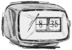
    As far as my question ... I'm trying to figure out what the component indicated below is and does.
    The video shows it better in place. The board at top is just the DC input. The wires to the device come off the board.


    Click image for larger version  Name:	arrow.jpg Views:	0 Size:	61.2 KB ID:	27238

    See the Video

    Click image for larger version  Name:	thumbnail.jpg Views:	0 Size:	404.8 KB ID:	27229
    ~ Mackey Site Administrator
    If you have any questions/comments Contact Me
    If you're not a member, you should consider joining!

    #2
    Very creative fix. I never thought about adding a wire. This method looks easier that the superglue/baking soda mix. Great post with the video.

    Comment


      #3
      Originally posted by Engineer
      Oh, nice. I have done this exact method on the super-big tiles of a Cifra 3 and the Emerson "BigTime" (with the Copal movement and tiles) and it seemed to work. Your method is actually nicer than mine was, honestly. Cleaner! GOOD WORK!

      I am not sure what the other item is that you pointed out. The view of it wasn't good enough to see in greater detail. It isn't a rectifier since DC is already coming in and only a single positive going in and neg coming out. It is exposed on the side towards the tiles so I was thinking maybe it was a photo-electric sensor?

      Edit: You can put a DMM across it while powered on and see if the voltage changes when you cover the exposed side. Voltage will be pretty low.
      Thanks. Was wondering what you thought. I just can't imagine a functional purpose that it would serve. It has both negative and positive going to it. If you got a closer look at the circuit board that is clear. What in the world would sending power to a device accomplish? The TWEMCO QT-30 that I just reviewed on YouTube (The Yoshitoma Nara Walk on Clock) has the same set up but no mystery device.
      I'm going to open that clock back up and see if I can get more a more clear picture of what is going on.

      ~ Mackey Site Administrator
      If you have any questions/comments Contact Me
      If you're not a member, you should consider joining!

      Comment


        #4
        Click image for larger version

Name:	deviceout.jpg
Views:	147
Size:	128.6 KB
ID:	27247
        The little mystery device just pops right out of the frame. The inside towards the tiles (hollow) is negative only. The outside (flat) surface is positive.
        On the circuit board 1.5V comes in, obviously. The pos and neg leads that go to the device has the negative After the Chip. On the board
        there is a voltage drop to 0.77 V after the chip. This is the same voltage across the mystery device.

        Click image for larger version

Name:	board.jpg
Views:	136
Size:	182.6 KB
ID:	27248

        The board is inaccessible when the clock is assembled. So I'm thinking that thinking that all this device is, is a way to check to make sure that the board is functioning properly after the clock as been assembled.

        The only reason I wanted to know was to see if these could mechanisms could be used in the QT-30 (that do Not have the mystery device). They clearly could. Seems that this could be removed if needed. I cannot find the mechanism on sale online. Most quartz clock mechanisms are square.

        Anyway. Let me know if I'm wrong. Thanks for making me look harder.

        ~ Mackey Site Administrator
        If you have any questions/comments Contact Me
        If you're not a member, you should consider joining!

        Comment


          #5
          Originally posted by Engineer
          Seems like a strange and excessive part just to check the clock for functionality at the factory. So, if there is a voltage drop across it that means it is acting like a resistor, but it could be a diode, maybe. But a strange looking one. Why is it in a little plastic mount? Why is it there at all? It is tied into the traces going into the epoxy covered time-keeping chip. That is the black dome-like structure on the board.

          I guess you could try to de-solder it to see how the behavior changes. While out of circuit you could test it on diode mode on your multimeter if it has one to see if it is one of those.
          The voltage drop is not across the device. It is after the chip on board. There's no current flowing through the device at all. It just has access points for pos and neg.
          ~ Mackey Site Administrator
          If you have any questions/comments Contact Me
          If you're not a member, you should consider joining!

          Comment


            #6
            Just saw this video, lol. I just fixed two of my tiles using the super glue and backing soda method. It worked great for me. But good to know there is a 2nd way of fixing them.

            Comment


              #7
              Originally posted by Jarcamp View Post
              Just saw this video, lol. I just fixed two of my tiles using the super glue and backing soda method. It worked great for me. But good to know there is a 2nd way of fixing them.
              I'm glad that worked for you. I'm not against that way either (I did kind of invent it, so anyway). It's such a common problem, unfortunately. It's nice to be able to keep these things going anyway we can.
              Thanks for joining the forum, by the way!
              ~ Mackey Site Administrator
              If you have any questions/comments Contact Me
              If you're not a member, you should consider joining!

              Comment

              Working...
              X