


An adventurous repair involving a gorilla and a hammer! ;-)
A while ago I bought a Kundo 2000 SLR and an AEG SWG. Both have a similar Kundo mechanism and both had the same issue: the first gear after the motor was broken. As I learned from flip clock_nl this is a very common issue with these clocks. The plastic used in this gear disintegrates over time and becomes brittle and squishy at the same time (sounds odd, but I don’t know how else to describe it). Looking for an original replacement does not make much sense as all gears out there are either broken or about to break. Instead I decided to reconstruct the gear from parts I could find on the internet. Here is what I did:
Step 1: get the gear out
As so many clocks these are not built to be taken apart. The mechanism consists of a clock section on the left and an alarm section on the right. The two sections are connected by:
- three metal bars,
- an axis or in case of the Kundo 2000 SLR with the more luxury double wheel alarm mechanism two coaxial axis,
- the circuit board at the back. Bits of the frame stick through the board and are then twisted. For the double wheel alarm mechanism there are also two soldering joints.
With the Kundo I tried to remove only the alarm section. After this it is still far from easy to remove the motor/gearbox assembly, and it has a major drawback: the alarm gets out of sync. Since this is the complicated double wheel alarm mechanism I spent hours getting that synced up again. So, don’t do this!
That lesson learned, on the AEG I left the two sections connected and only removed the circuit board by untwisting the metal lips. Then removed one pin holding the motor/gearbox assembly and the assembly can simply be removed. Much easier!
Step 2: get the gear dimensions
From the number of teeth and the outer diameter I calculated the module (a measure for the size of the teeth) using this online tool: https://www.technobotsonline.com/gea...alculator.html
For both gears the estimated module is 0.3. You need the module for the next step because gears on offer on the internet are usually denoted by the number of teeth and the module.
Step 3: find the gears
Finding an exact match for the double gear would be mission impossible, so I searched for the two individual gears with the plan to construct a double gear from that. After a veeeery looong search on the internet found the gears: one (a model helicopter part) from China, the other (a model train part) from the Czech Republic. Appears that in module 0.5 there is plenty on offer, but in this smaller teeth size (module 0.3) they are really rare, at least in plastic. There is some more choice in brass, but I’m afraid a brass gear will wear out the next plastic gear too quickly and I prefer to work with plastic.
- 56 teeth, module 0.3: https://www.xiphorix.com/en/m03-56-tooth-plastic-gear (At the moment of posting this was offline. Hope it gets back. If not and you need a gear: just give me a call. I still have plenty).
- 16 teeth, module 0.3: http://www.pojezdy.eu/eshop/pro-osu-...ul-0-3-mm.html
Step 4: adjustments to the large gear
Two things needed to be done to the large gear:
- Increasing the inner diameter to 2 mm. This is easily done using a drill and file.
- Filing a bit of the protrusion around the axle on the motor side to make it fit close enough to the motor.
Step 5: adjustments to the small gear
The small gear also needed a small increase of the inner diameter. The size I found is a 2A (A = tight fit) whereas I needed a 2B (B = loose fit). Again easily corrected using drill and file.
When I then trial fitted the gear it appeared to be a bit too small. The gears did connect, but only just.
Since this would probably not work for long I was more or less back at square one. I tried to think up solutions and could not think of any until despair made me try a crazy idea:
hit it with a hammer!

As insane as it may sound there was a theory behind it: if I flatten it, it must get wider. My sane mind though expected the gear would crack or deform too much. But it didn’t, it actually worked!
Step 6: building the connecting neck
To build the neck I used a wonderful material that I recently discovered: Gorilla Plastic! http://www.gorilla-plastic.de (I believe similar stuff is available from other brands). This is modelling plastic with a low melting point. It becomes mouldable at 65ºC. You heat it up using boiling water, and then depending on the amount have one to several minutes time to mould it. Although still hot you can hold it with your hands since it doesn’t not conduct heat very well. If applied hot enough it will stick to other plastics. When it cools down it becomes hard and strong and you can work it mechanically. Its best property though is that the process is completely reversible! So if you make a mistake you can just heat it up again to correct it. Also leftovers can simply be reused. I see many uses for this stuff: making replacement parts, braces for broken bits, creating a (temporary) mould, etc. I already applied it in two other repairs.
Back to this repair:
It takes some practice to work with this gorilla plastic in the small quantity. Luckily the proces is fully reversible so you can practice as much as you need. This is the approach that in the end worked best for me:
- I used a nail as a temporary axle for alignment and first fitted the large gear on that.
- Then I heat up a fair amount of gorilla plastic, much more than needed in the end. I do this because it will only stick well to plastic when dry and hot enough. A small quantity cools down too quickly.
- After taking it out of the water, kneed it through and when it is dry, stick it on the nail and mould it against the large gear.
- When it cools down and sticks well to the gear throw the whole assembly back in boiling water. (The gears are made of Polyoxymethylene (POM) which has a melting point of 172ºC, so it is safe to throw it in boiling water.)
- When hot again, take it out of the water and pull off the excess material. Then fit the small gear and push it in to the right height. You can use the old gear to check the height is correct. Be careful to not get the plastic in the teeth.
- Repeat the last two steps until you get it right.
- Let it cool down a bit.
- When it is firm enough but not fully cooled, remove the nail.
- After it is fully cooled clean up the hole for the axle using drill and/or file if needed.
And here is are the results:
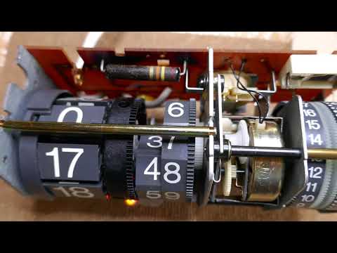
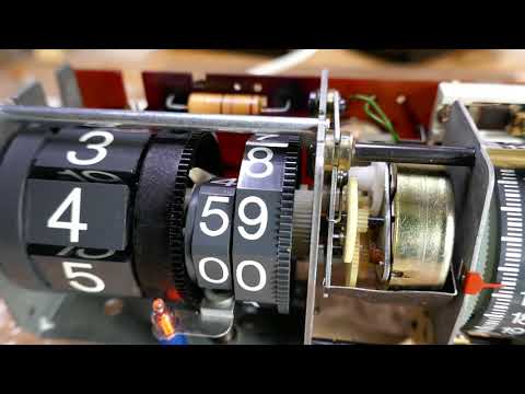
Final step: assemble and test
Both gears in action:
The two rescued clocks:

 Include some pictures if possible, that is often very helpful.
Comment